HOME PRODUCTS Protection,Automation & Control Protection&Control Circuit Breaker Protection
-
SERVICES
 NEWS
NEWS  EVENT CALENDOR
  CONTACT US
-
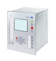
PCS-921S Breaker Failure Relay
PCS-921S breaker failure relay integrates various protection functions, which is designed for the single- or three-pole circuit breaker on all voltage levels and provides comprehensive protection and control solutions. With its flexibility and the powerful PCS-Studio configuration tool, PCS-921S offers future-oriented system solutions with high investment security and low operating costs.

- Protection and Control Supervision Recording Measurement Synchrophasor measurement Communication protocol Communication interface
-
Six stages phase overcurrent protection (67P, 50/51P)
Six stages earth-fault protection (67G, 50/51G)
Two stages negative-sequence overcurrent protection (67Q, 50/51Q)
Two stages phase undervoltage protection (27P)
Two stages phase overvoltage protection (59P)
Two stages negative-sequence overvoltage protection (59Q)
Two stages residual overvoltage protection (59G)
Four stages overfrequency protection (81O)
Four stages underfrequency protection (81U)
Four stages frequency rate-of-change protection (81R)
One stage undercurrent protection (37)
Breaker failure protection (50BF)
Dead zone protection (50DZ)
Pole discrepancy protection (62PD)
Auto-reclosing (79)
Switchgear control
Synchronism Check (25)
Voltage selection
Voltage and current drift auto adjustment
CT circuit failure supervision
VT circuit failure supervision
Trip/Close coil supervision
Self-diagnostic
DC power supply supervision
System frequency supervision
Event Recorder including 1024 disturbance records, 1024 binary events, 1024 supervision events, 256 control logs and 1024 device logs.
64 disturbance waveforms records (The file format of disturbance recorder is compatible with international COMTRADE file.)
64 high-frequency waveforms records (The file format of disturbance recorder is compatible with international COMTRADE file.)
Current and voltage measurement at a 2.4KHz sampling rate
Current and voltage measurement at a 9.6KHz sampling rate
Energy metering (active and reactive energy are calculated in import respectively export direction)
Power (Apparent/Real/Reactive)
Power factor
Frequency
Synchronize with the GPS time by IRIG-B time source
Calculate synchronized phasors, including: Ua, Ub, Uc, U1, U2, U0, Ia, Ib, Ic, I1, I2, I0
Calculate analog values, including: active power (P), reactive power (Q), frequency, ROCOF (df/dt)
Transmit binary status of the IED to PDC (Phasor Data Concentrator) according to IEEE C37.118 standard
Realize high accurate measurement of the phasors and analogs according to the IEEE C37.118.1-2011 and IEEE C37.118.1a-2014 standard.
Communicate with PDC according to IEEE C37.118-2005 and IEEE C37.118.2-2011
IEC 61850 Editions 1 and 2
IEC 60870-5-103
DNP3.0
Modbus
IEC 62439 Parallel Redundancy Protocol (PRP)
IEC 62439 High-availability Seamless Redundancy (HSR)
IEEE 802.1w Rapid Spanning Tree Protocol (RSTP)
2 or 4 100Base-TX copper Ethernet ports for SCADA communication
2 or 4 100Base-FX optical Ethernet ports for SCADA communication
2 RS-485 serial ports for SCADA communication
Extendable 1000Base-SX optical Ethernet port for PRP and HSR
1 RS-485 serial port for clock synchronization
1 TTL serial port for clock synchronization
1 BNC port for clock synchronization
1 optical fiber port (ST-connector) for clock synchronization
1 front RJ-45 port for debugging
1 rear RJ-45 port for debugging