HOME PRODUCTS Protection,Automation & Control Protection&Control Transmission Line Protection
-
SERVICES
 NEWS
NEWS  EVENT CALENDOR
  CONTACT US
-
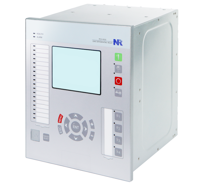
PCS-931S Line Differential Relay
PCS-931S line differential relay integrates main and back-up protection functions, which is designed for overhead line, cables and hybrid transmission lines of various voltage levels and provides comprehensive protection and control solutions. With its flexibility and the powerful PCS-Studio configuration tool, PCS-931S offers future-oriented system solutions with high investment security and low operating costs.

- Protection and Control Synchrophasor measurement Measurement Recording Supervision Pilot channel scheme Communication interface Communication protocol Digital application Clock synchronization Cybersecurity
-
High-speed DPFC distance protection (21D)
Six zone phase-to-phase distance protection (21L)
Six zone phase-to-ground distance protection (21L)
DPFC current differential protection (87L)
Steady-state current differential protection (87L)
Neutral current differential protection (87L)
Pilot distance protection (85)
Pilot directional earth-fault protection (85)
Unique power swing blocking releasing logic (PSBR)
Six stages phase overcurrent protection (67P, 50/51P)
Six stages earth-fault protection (67G, 50/51G)
Two stages negative-sequence overcurrent protection (67Q, 50/51Q)
Switch-onto-fault (SOTF) logic
Two stages phase undervoltage protection (27P)
Two stages phase overvoltage protection (59P)
Two stages negative-sequence overvoltage protection (59Q)
Two stages residual overvoltage protection (59G)
Four stages overfrequency protection (81O)
Four stages underfrequency protection (81U)
Four stages frequency rate-of-change protection (81R)
Two stages reverse power protection (32R)
Two stages thermal overload protection (49P)
One stage undercurrent protection (37)
Breaker failure protection (50BF)
Flashover protection (50F)
Dead zone protection (50DZ)
Broken conductor protection (46BC)
Pole discrepancy protection (62PD)
Stub differential protection (87STB)
Out-of-step protection (78)
Auto-reclosing (79)
Switchgear control
Synchronism Check (25)
Voltage selection
Voltage and current drift auto adjustment
Single-ended impedance-based fault location
Travelling-Wave fault location including single-ended travelling-wave-based method and double-ended travelling-wave-based method
Synchronize with the GPS time by IRIG-B time source
Calculate synchronized phasors, including: Ua, Ub, Uc, U1, U2, U0, Ia, Ib, Ic, I1, I2, I0
Calculate analog values, including: active power (P), reactive power (Q), frequency, ROCOF (df/dt)
Transmit binary status of the IED to PDC (Phasor Data Concentrator) according to IEEE C37.118 standard
Realize high accurate measurement of the phasors and analogs according to the IEEE C37.118.1-2011 and IEEE C37.118.1a-2014 standard.
Communicate with PDC according to IEEE C37.118-2005 and IEEE C37.118.2-2011
Supporting P Class or M Class measurement (user selectable)
Measurement of up to 32 binary status (user configurable)
Output of synchrophasor with timestamp, support of multiple protocols (TCP, TCP-UDP, UDP) and multiple data rates (2f0, f0, f0/2) for maximum 4 clients (PDC)
Current and voltage measurement at a 2.4KHz sampling rate
Current and voltage measurement at a 9.6KHz sampling rate
Travelling wave current measurement at a 1MHz sampling rate
Energy metering (active and reactive energy are calculated in import respectively export direction)
Power (Apparent/Real/Reactive)
Power factor
Frequency
Current, voltage and active/reactive power calibration
Event Recorder including 1024 disturbance records, 1024 binary events, 1024 supervision events, 256 control logs and 1024 device logs.
64 disturbance waveforms records (The file format of disturbance recorder is compatible with international COMTRADE file.)
64 travelling wave fault location (TWFL) records (The file format of disturbance recorder is compatible with international COMTRADE file.)
64 high-frequency waveforms records (The file format of disturbance recorder is compatible with international COMTRADE file.)
CT circuit failure supervision
VT circuit failure supervision
Trip/Close coil supervision
Self diagnostic
Pilot communication channel supervision
DC power supply supervision
Channel status statistic
System frequency supervision
Circuit breaker supervision (contact travel time, interrupted current, trip counter, remaining life, accumulated abrasion, etc.)
Optional single- or dual- pilot channels (fiber optic)
Support G.703 and C37.94
2 or 4 100Base-TX copper Ethernet ports for SCADA communication
2 or 4 100Base-FX optical Ethernet ports for SCADA communication
2 RS-485 serial ports for SCADA communication
Extendable 1000Base-SX optical Ethernet port for PRP and HSR
1 RS-485 serial port for clock synchronization
1 TTL serial port for clock synchronization
1 BNC port for clock synchronization
1 front RJ45 port for debugging
1 rear RJ45 port for debugging
IEC 61850 Editions 1 and 2
IEC 60870-5-103
DNP3.0
Modbus
IEC 62439 Parallel Redundancy Protocol (PRP)
IEC 62439 High-availability Seamless Redundancy (HSR)
IEEE 802.1w Rapid Spanning Tree Protocol (RSTP)
IEC 61850 MMS Server
IEC 61850-8-1 GOOSE
IEC 61850-9-2LE SV
4 100Base-TX electrical or 100Base-FX optical Ethernet port (station level)
Extendable 100Base-FX optical Ethernet port (process level)
Extendable 1000Base-SX optical Ethernet port (process level)
IRIG-B: IRIG-B via serial port (RS-485 or TTL level) or BNC port (TTL level)
PPS: Pulse per second (PPS) via serial port (RS-485 or TTL level), BNC port (TTL level) or binary input
IEEE 1588: Clock message based on IEEE 1588 via Ethernet network
SNTP: Unicast (point-to-point) & broadcast SNTP mode via Ethernet network
Clock messages: IEC 60870-5-103 protocol, Modbus protocol and DNP3.0 protocol
NERC CIP
IEC 62351
IEC 62443
IEEE 1686